A "dish" antenna has the optimum form for collecting
electromagnetic radiation and bringing it to a focus. The reflecting
surface is based on a three-dimensional shape called a
paraboloid,
and has the unique property of directing
 all incoming wave fronts prependicular
to its axis, in phase, to a point
focus. Reflective antennas are
generally made of steel, aluminum,
or fiberglass with an embedded
reflective foil.
all incoming wave fronts prependicular
to its axis, in phase, to a point
focus. Reflective antennas are
generally made of steel, aluminum,
or fiberglass with an embedded
reflective foil.
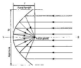
The location of the focal point is a property of the geometry of the dish and is independent of the radiation wavelength. The diagram here shows the basic configuration and identifies the focal point, focal length, and aperture.
The paraboloid is defined as the set of points equidistant from a fixed point (the focus) and a plane, (the directrix). It is straight forward to show that this geometric configuration can work for our purpose. The diagram below illustrates the process involved.
Electromagnetic energy radiating from an omni-directional source
consist of spherical waves of increasing radius. At great distances
these are approximated by planar fronts and are called plane
waves. We see that plane waves coming from the
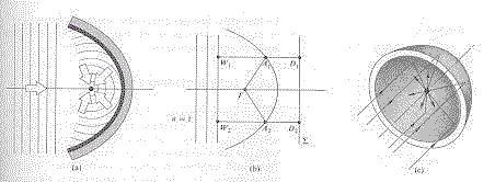 left are reformed
after reflection
into converging
spherical waves.
In order for the
plane waves to ultimately converge on some point F, the
path lengths for all parts of the waves must be equal. In the
center of the diagram above we have two arbitrary points A1
and A2, on the surface of the reflector. We envision two
points riding on a wave crest and tracing out rays which describe
their path. For rays parallel to the axis of the paraboloid and
incident to A1 and A2, we have
left are reformed
after reflection
into converging
spherical waves.
In order for the
plane waves to ultimately converge on some point F, the
path lengths for all parts of the waves must be equal. In the
center of the diagram above we have two arbitrary points A1
and A2, on the surface of the reflector. We envision two
points riding on a wave crest and tracing out rays which describe
their path. For rays parallel to the axis of the paraboloid and
incident to A1 and A2, we have
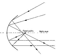 angles other than parallel to the main
axis are reflected so as to miss the
focal point altogether.
There is a "head unit" (also
called a "feed horn") placed at the
focal point of the antenna. It is said
to illuminate the dish; a term is used
even if the antenna is
designed for reception only, (since reception is basically the
reverse process of transmission, descriptions of antenna theory
seem to switch, at a whim, between transmission and reception
terminology).
The above argument was intuitive, but not totally convincing, (do you see
why?).
I have a couple Maple programs for you to enjoy - you can make your own
reflecting antenna systems and watch the rays bounce to a focus, just like
we claim they should - but this is still a formational type reasoning.
Sophisticated math scolars will expect a formal, analytical
proof about now. Please click here to view said
proof. I am rather proud of it. Or click below to bypass it.
angles other than parallel to the main
axis are reflected so as to miss the
focal point altogether.
There is a "head unit" (also
called a "feed horn") placed at the
focal point of the antenna. It is said
to illuminate the dish; a term is used
even if the antenna is
designed for reception only, (since reception is basically the
reverse process of transmission, descriptions of antenna theory
seem to switch, at a whim, between transmission and reception
terminology).
The above argument was intuitive, but not totally convincing, (do you see
why?).
I have a couple Maple programs for you to enjoy - you can make your own
reflecting antenna systems and watch the rays bounce to a focus, just like
we claim they should - but this is still a formational type reasoning.
Sophisticated math scolars will expect a formal, analytical
proof about now. Please click here to view said
proof. I am rather proud of it. Or click below to bypass it.