Parabolic Reflecting Antennas
Actual antennas are not perfect. Some unwanted signals will enter
the head unit. Waves are diffracted and scattered at the rim of
the dish. Unwanted
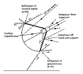 signals may thus converge on the
focal point. Surface irregularities
cause reflection errors. The head
unit and support structure block
signals. Galactic noise will enter
along with the desired signal
(background radiation from the
"big-bang" is most pernicious at
10-15
GHz5. The sun and the earth are also sources of electrical noise
at all frequencies). Signals may be absorbed rather than reflected
by the antenna dish. Some of these real life problems are illustrated
in the diagram at right.
In spite of these complications, we achieve accurate approximations
and considerable understanding through our idealized geometric
models. So we shall study the shapes of the antenna in detail
here.
We all know how to derive the formula for a parabola. But for quick
reference, here it is:
y = x^2/4p (#)
With x = the radius of the dish, (i.e. aperture/2),
we may rearrange (#) above as follows,
f = D^2/16d (!)
Where D is the aperture and d is the depth of the
dish. In this way, we may locate the focal point, f, given a particular
dish. These parameters are easy to measure and the calculation
is easy to perform by hand.
signals may thus converge on the
focal point. Surface irregularities
cause reflection errors. The head
unit and support structure block
signals. Galactic noise will enter
along with the desired signal
(background radiation from the
"big-bang" is most pernicious at
10-15
GHz5. The sun and the earth are also sources of electrical noise
at all frequencies). Signals may be absorbed rather than reflected
by the antenna dish. Some of these real life problems are illustrated
in the diagram at right.
In spite of these complications, we achieve accurate approximations
and considerable understanding through our idealized geometric
models. So we shall study the shapes of the antenna in detail
here.
We all know how to derive the formula for a parabola. But for quick
reference, here it is:
y = x^2/4p (#)
With x = the radius of the dish, (i.e. aperture/2),
we may rearrange (#) above as follows,
f = D^2/16d (!)
Where D is the aperture and d is the depth of the
dish. In this way, we may locate the focal point, f, given a particular
dish. These parameters are easy to measure and the calculation
is easy to perform by hand.
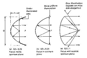 A dish antenna
may be shallow or deep
depending on the slice of
the paraboloid envisaged
during manufacture. The
figure to the right
illustrates three
possibilities.
Practically
speaking, it is difficult to illuminate the dish uniformly with
the feed inside the aperture plane (A). This is because waves
arriving from opposite directions tend to cancel through superposition.
This is also why our eye peers in one direction only. On the other
hand, placing the focal point well outside the aperture plane
increases the chance of receiving unwanted signals and noise.
The feed point is not well shielded, and this configuration increases
the chance of transmission loss. Signals from the feed horn may
miss the edge of the dish. This effect is known as "over-illumination".
The ratio of the focal distance to the dish diameter, denoted
f /D is a standard component parameter used by systems
installers. For a feed point at the aperture plane, parabola
geometry dictates that radio to be 0.25. Observe that if f
= d in (!), we have
f = D^2/16f
f^2 = D^2/16
f=D/4.
Therefore, f /D = .25, as we said.
Deep dishes with low f /D ratios tend to have higher
efficiency and are more shielded from noise. In practice, the
f /D ratios are greater than .25 but less than 1
for manufacturing reasons. It is much easier to fabricate,
finish, and transport a shallow dish. There are also practical problems
with illuminating angles greater than 180 degrees.
The problem of over-illumination
is countered by the design of the head unit, which must compensate
by restricting the beamwidth there.
The gain of a dish antenna, (the ratio of output to input power
and denoted Ga) is dependent on its size and the length of the
waves being transmitted/received. An expression for the gain which
takes into account the efficiency (rho) of the system is:
Ga = 10 ln(((pi*d)^2*rho)/lam^2 dB
Where d = the reflector aperture (m)
rho = the normalized antenna efficiency (typically .60-.80)
lam = wavelength of radiation (m)
and dB indicates decibels, the usual units for power.
The expression above comes from solutions to Maxwell's equations.
We can see why dish antennas are only common for work with very
short waves. Note that for a given efficiency, gain for a parabolic
reflector increases as the aperture increases and as the radiation
wavelength decreases. We generally find dish antennas used in
the micro-wave range of frequencies, where 1-40 GHz corresponds
to wavelengths about 30 cm - 7.5 mm.
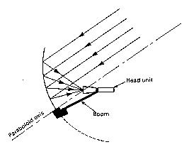
Typical parabolic type antennas, called "prime focus"
antennas, position the focal point at the center of the dish.
Most large antennas use this method because of the mechanical
stability inherent with this geometry. For medium to high power
systems operating at or above 10 GHz, this configuration is rare.
For these small antennas, the offset focus configuration is most
often used
A dish antenna
may be shallow or deep
depending on the slice of
the paraboloid envisaged
during manufacture. The
figure to the right
illustrates three
possibilities.
Practically
speaking, it is difficult to illuminate the dish uniformly with
the feed inside the aperture plane (A). This is because waves
arriving from opposite directions tend to cancel through superposition.
This is also why our eye peers in one direction only. On the other
hand, placing the focal point well outside the aperture plane
increases the chance of receiving unwanted signals and noise.
The feed point is not well shielded, and this configuration increases
the chance of transmission loss. Signals from the feed horn may
miss the edge of the dish. This effect is known as "over-illumination".
The ratio of the focal distance to the dish diameter, denoted
f /D is a standard component parameter used by systems
installers. For a feed point at the aperture plane, parabola
geometry dictates that radio to be 0.25. Observe that if f
= d in (!), we have
f = D^2/16f
f^2 = D^2/16
f=D/4.
Therefore, f /D = .25, as we said.
Deep dishes with low f /D ratios tend to have higher
efficiency and are more shielded from noise. In practice, the
f /D ratios are greater than .25 but less than 1
for manufacturing reasons. It is much easier to fabricate,
finish, and transport a shallow dish. There are also practical problems
with illuminating angles greater than 180 degrees.
The problem of over-illumination
is countered by the design of the head unit, which must compensate
by restricting the beamwidth there.
The gain of a dish antenna, (the ratio of output to input power
and denoted Ga) is dependent on its size and the length of the
waves being transmitted/received. An expression for the gain which
takes into account the efficiency (rho) of the system is:
Ga = 10 ln(((pi*d)^2*rho)/lam^2 dB
Where d = the reflector aperture (m)
rho = the normalized antenna efficiency (typically .60-.80)
lam = wavelength of radiation (m)
and dB indicates decibels, the usual units for power.
The expression above comes from solutions to Maxwell's equations.
We can see why dish antennas are only common for work with very
short waves. Note that for a given efficiency, gain for a parabolic
reflector increases as the aperture increases and as the radiation
wavelength decreases. We generally find dish antennas used in
the micro-wave range of frequencies, where 1-40 GHz corresponds
to wavelengths about 30 cm - 7.5 mm.
Typical parabolic type antennas, called "prime focus"
antennas, position the focal point at the center of the dish.
Most large antennas use this method because of the mechanical
stability inherent with this geometry. For medium to high power
systems operating at or above 10 GHz, this configuration is rare.
For these small antennas, the offset focus configuration is most
often used
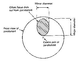 The figures above show that the offset focus dish is really a
section cut out of a much larger parabola (this does not imply
that they are manufactured this way!).
The figures above show that the offset focus dish is really a
section cut out of a much larger parabola (this does not imply
that they are manufactured this way!).
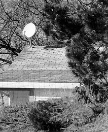
This geometry has several
advantages. The feed head is
out of the way of incoming
signals and is inclined away
from the earth toward a cool
sky. Further, snow and other
debris can slide off the dish
more easily. We see a specimen
of this type in the photo
above.
As we noted, system efficiency is affected by the conformity
of the actual
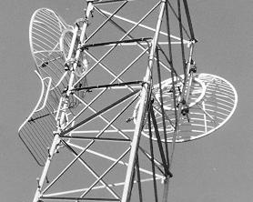
reflecting surface to the ideal
model: the parabola. However, large
local deviations from this shape are
not as critical as small deviations
overall. Above we see reflectors
which have large voids in them. They
continue to
function efficiently because the size of the voids are small compared
to the length
of the waves which they reflect.
The cylindrically parabolic
reflector focuses in one spatial
direction only. This makes aiming
simpler, but reduces gain.
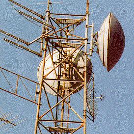
In the photo above we have
another type of antenna. It is a
radio lens, analogous to an optical
lens. Although this paper is not
describing refracting components,
it is interesting to note that
these lenses have voids in their
structure as well, just as the
reflector mounted below it does.
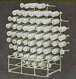
Here we see an actual
lens of this type. The radiation it focuses has a wavelength which
is comparable to the spaces
between the plates in the
lens.
The fact that large local
deviations are insignificant to
performance is good news for any amateur
who wants to build a parabolic antenna.
Precision on a small scale is not a
limiting concern. As amateur astronomers
discover when grinding their mirrors, the
"Rayleigh limit" for telescopes is that
little
gain increase is realized by making the mirror accuracy greater
than 1/8 wavelength. An eighth wave is 3.4 inches at 432 MHz, 1.1 inches
at
1296 MHz and 0.64 inch at 2300 MHz, (UHF and microwave radio frequencies,
respectively).
Below, we have a photo of a common design used by amateurs.
The so-
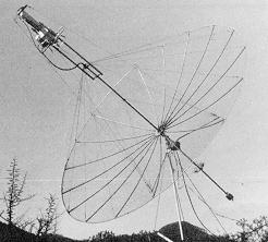
called "stressed" parabolic antenna. It
is lightweight, portable, and easy to
build. Each spoke is basically a
cantilevered beam with end loading. The
equations of beam bending predict a near
perfect parabolic curve for very small
deflections (actually any engineering
student will remind you that an end loaded cantilever deforms as a cubic
function of distance from its support - but cubics are enough like
quadradics for small displacements). However, here the
deflections are not that small and the
loading
is not perpendicular. The uncorrected surface is enough for 432
and 1296 MHz bands, but bending the supports a little to fit a pattern is
a good
suggestion.
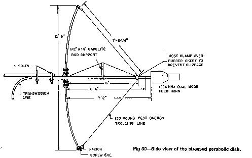
By placing the
transmission line inside the
central pipe that supports the feed
horn, the area of the shadows or
blockages on the reflector surface
is much smaller than in other
feeding and supporting systems,
thus increasing
More