Preliminaries:
I expect this to be a first in a series of experiments dealing with electrometric radiation. I would place it immediately after a consideration of induction and before optics.
Prelab Questions:
1) Explain the difference between induction and electromagnetic radiation.
2) How would you be able to generate high frequency electromagnetic oscillations (greater than 1,000 Hz)? (Leading to Fessenden's mechanical generator, Hertz's spark gap, and DeForest's vacuum tube.)
3) Why do you suppose spark-gap radio transmitters are outlawed by the FCC?
____________________________________________
Physics ### lab
Electromagnetic
Propagation - Hertzian waves
Purpose: The purpose of this experiment is to investigate Hertz' original experiment, whereby he reported to have detected radio waves.
Equipment: For this experiment, you will need:
* High voltage generator, (coil)
* Dipole radiator with spark gap.
* Loop receiving antenna with spark gap.
Background:
In 1858 Wilhelm Feddersoen (1832-1918) German physics professor at Leipzig demonstrated experimentally that the sparks jumping between the spheres of a Ruhmkorff coil oscillated and that they could generate electric waves of long wavelength. In 1861, he used the rotating mirror designed by British physicist Charles Wheatstone (1802-1875) to record the phenomenon on a photographic plate.
Using mathematical models, James Clerk Maxwell had suggested that two
different types of electrical disturbances could possibly exist in Nature. One
type was a longitudinal electric wave which required alternating concentrations
of densified and rarefied pulsations of electrostatic fields that moved along a
single vector (today, we refer to these as standing waves or scalar waves).
Maxwell ultimately rejected this idea because he was convinced that this type
of wave propagation was impossible to achieve, but his assumption was
erroneous.
Maxwell’s second wave postulation was that of a transverse electromagnetic wave that exhibited a rapid alternation of electric fields along a fixed axis that radiated away from its point of origin at the speed of light and was detectable at great distances. Maxwell had more faith in the existence of this type of wave and encouraged experimenters to look in this direction. It was the discovery of this type of wave that Hertz laid claim to.
In 1888 Hertz drew an influential series of diagrams to accompany his 1889 paper on dipole radiation, which was translated as "The forces of electric oscillations, treated according to Maxwell’s theory". Hertz took a great deal of care with these drawings, (below).
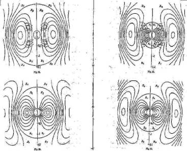
You can see that the focus of Hertz's discussion is on the radiated EM field. He spends little time discussing the actual dipole antenna or the fields immediately close to its surface.
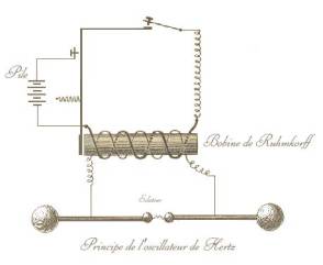
Below is a schematic diagram of Hertz's transmitter. You can see that he used a Ruhmkorff coil to induce a huge voltage across the spark-gap in the antenna.
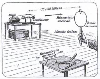
You see, below, the setup for detecting Hertzian waves.
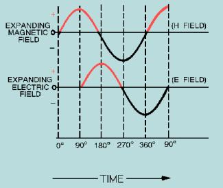
The graph shown in the figure below
shows the relationship between the magnetic (H) field and the electric (E)
field plotted against time. Note that the two fields are 90 degrees out of
phase with each other in time. It is also true that the two fields
around the antenna are displaced 90 degrees from each other in space.
The H field exists in a plane perpendicular to the antenna. Its field lines
circle the axis of the antenna. The E field exists in a plane parallel with the
antenna. Its field lines arc along the length of the antenna.
Phase
Relationship of Induction Field Components
All the energy supplied to the
induction field is returned to the antenna by the collapsing E and H fields. No
energy from the induction field is radiated from the antenna. Therefore, the
induction field is considered a local field and plays no part in the
transmission of electromagnetic energy. The induction field represents only the
stored energy in the antenna and is responsible only for the resonant effects
that the antenna reflects to the generator.
The diagram below is a simple
picture of an E field detaching itself from an antenna. (The H field will not
be considered, although it is present.) In view A the voltage is maximum and
the electric field has maximum intensity. The lines of force begin at the end
of the antenna that is positively charged and extend to the end of the antenna
that is negatively charged. Note that the outer E lines are stretched away from
the inner lines. This is because of the repelling force that takes place
between lines of force in the same direction. As the voltage drops (view B),
the separated charges come together, and the ends of the lines move toward the
center of the antenna. But, since lines of force in the same direction repel
each other, the centers of the lines are still being held out.
Radiation
from an Antenna
As the voltage approaches zero (view
B), some of the lines collapse back into the antenna. At the same time, the
ends of other lines begin to come together to form a complete loop. Notice the
direction of these lines of force next to the antenna in view C. At this point
the voltage on the antenna is zero. As the charge starts to build up in the
opposite direction (view D), electric lines of force again begin at the
positive end of the antenna and stretch to the negative end of the antenna.
These lines of force, being in the same direction as the sides of the closed
loops next to the antenna, repel the closed loops and force them out into space
at the speed of light. As these loops travel through space, they generate a
magnetic field in phase with them.
Since each successive E field is
generated with a polarity that is opposite the preceding E field (that is, the
lines of force are opposite), an oscillating electric field is produced along
the path of travel. When an electric field oscillates, a magnetic field having
an intensity that varies directly with that of the E field is produced. The
variations in magnetic field intensity, in turn, produce another E field. Thus,
the two varying fields sustain each other, resulting in electromagnetic wave
propagation.
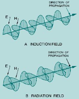
During this radiation process, the E
and H fields are in phase in time but physically displaced 90 degrees in space.
Each field supports the other, and neither can be propagated by itself. The
figure below shows a comparison between the induction field and the radiation
field.
E
and H Components of Induction and Radiation Fields
Procedure:
Work in teams of at least two people.
1) Assemble the apparatus as described above.
2) Close the switch to the coil in order to produce a high voltage spark between the legs of the dipole radiator.
3) View the minute resultant spark (in a dark room) in the gap of the receiving antenna.
4) Turn the receiving antenna 90° and try the experiment again. Record your ` observations.
5) Adjust the gap spacing and record your observations.
6) Adjust the voltage supplied to the coil (and thus the power of supplied to the spark) and record your observations.
Follow up Questions for Students:
1) How does the size of the antenna relate to the frequency of radio signal emitted?
2) Does the antenna radiate an electrical or magnetic field?
3) Would it be possible to design an antenna for either electric or magnetic radiation? How would they differ in design?
4) Why did the receiving antenna look different than the radiating antenna?
__________________________________
Comments
Students generally assume that radio wave transmitters need to be complicated systems of electrical components networked in some unfathomable arrangement. They should be surprised at the simplicity of this experiment.
I tried to copy Hertz's setup as closely as possible. I had trouble finding details of his apparatus. The Web pages I found with more than token information were written in German or higher math, (both languages I have difficulty with.)
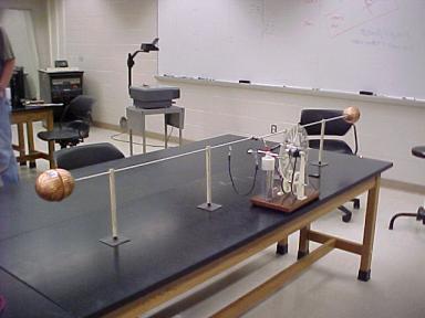
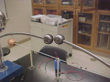
Above, you see the dipole radiator, Hertz's big invention. I tried to match his in size and appearance. I was surprised that they still sell copper float bulbs at the hardware store.
I used a Wimshurst Generator to supply the several kilovolt spark to the gap between the antenna legs. Nice spark, but not nearly enough power for the job.
Hertz used a Ruhmkorff coil. Wilhelm Feddersoen had already shown in 1858 that the sparks jumping between the spheres of a Ruhmkorff coil oscillated. Hertz figured that they could generate electric waves.
I positioned the receiving antenna away from the "near field". We wouldn't want to confuse induction with radiation.
This is a close-up of the gap in the receiving antenna. I used ball bearings. They don't look shiny anymore because I had to heat them up (anneal) before I could drill them. You can see the big capacitor on the table. I tried using that to store more energy. It didn't help. I couldn't get it to charge at all with that generator. I should have brought in a disposable camera.
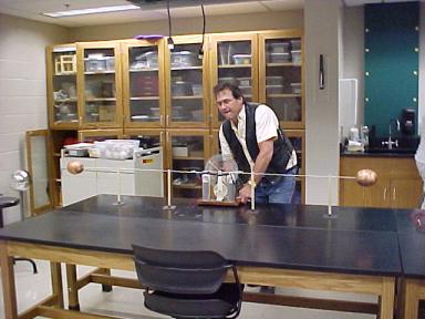
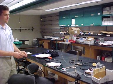
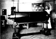
Here I am, working real hard. The sparks look cool. But even with the lights off, we couldn't see any spark in the receiver. I wasn't surprised. I would like to try a Ruhmkorff coil some day. Here's a picture (below) of a big one that maybe I can find on e-bay.
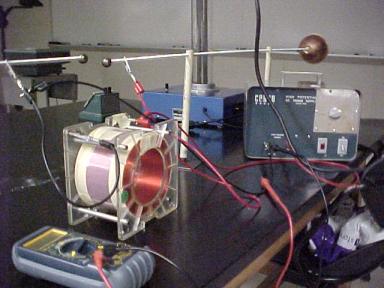
I did find an air-core inductor in the physics lab. I've made sparks with coils before and thought this was worth a shot. I fed DC to it. Then pulled the power. I hoped that the collapsing field would induce enough emf to jump powerfully. It didn't work.
So, my results were not good. I assume that I was not using enough power. I will try again with a large coil and higher current.
Another idea is to use a camera with the shutter open to record one or more sparks.
Sources
Radiant Energy:
Unraveling Tesla’s Greatest Secret
http://educate-yourself.org/fe/radiantenergystory.shtml
--------
Reflections
on Hertz and the Hertzian Dipole
Jed Z. Buchwald, MIT and the Dibner Institute for the History of Science and Technology
http://dibinst.mit.edu/DIBNER/DIConferences/OldConferences/Sloan/reflecti.htm
---------
HISTORICAL
EXPERIMENTATION
Taught in 1999 by Jed Buchwald at the Massachusetts Institute
of Technology
http://www.aip.org/history/syllabi/experiments.htm#Reading%20list
Which states:
o. Hertz propagation experiments as originally performed. Easy to set up once resonator and oscillator in hand.
---------
History
http://dspt.club.fr/antiqueR.htm
---------
Heinrich Rudolf HERTZ
http://dspt.club.fr/hertz.htm
--------
K14 Electric oscillations
http://kr.cs.ait.ac.th/~radok/physics/k14.htm
--------
RADIO WAVE PROPAGATION
http://www.tpub.com/neets/book10/40.htm
------
Heinrich Daniel
Ruhmkorff
http://chem.ch.huji.ac.il/~eugeniik/history/ruhmkorff.htm